.avif)

There are a variety of reasons for and ways in which pin connections are incorporated into structure and architecture. In structural engineering, pin connections are used to release flexural forces in the pin ended member at the location and in the axis of the pin. In architecture, pin connections are most often used as a means of tectonic expression; that is, to create a visual portrayal of the way in which the structure was constructed and the way that forces are resisted by the structure.
Our catalog provides design inspiration that may be useful to get started and to share with associates and clients.

When pin connections are specified for architectural reasons, the quality of the connection’s execution is important. Fabrication of pin connections at the ends of HSS members is difficult particularly when aesthetics are a concern as there must be adherence to particular AESS standards.

Cast Connex^® Universal Pin Connectors™ are sleek, clevis-type pre-engineered fittings. Their sculpted design provides smooth transitional geometry that is otherwise unachievable using standard fabrication practices. Universal Pin Connectors are a complete connection solution as they are supplied with the associated steel pins and electropolished stainless steel washers, cap plates, and cap screws. The connectors are available off the shelf in sizes to match standardized pipe ranging from 3.5-inch (88.9 mm) OD to 24-inch (610 mm) outer diameter. The connectors are a smart and affordable choice when compared against conventionally fabricated connections that attempt to meet a similar aesthetic as provided by the connectors. Moreover, the use of Universal Pin Connectors vastly simplifies the design, detailing, fabrication, and subsequent inspection and acceptance of critical AESS connections.
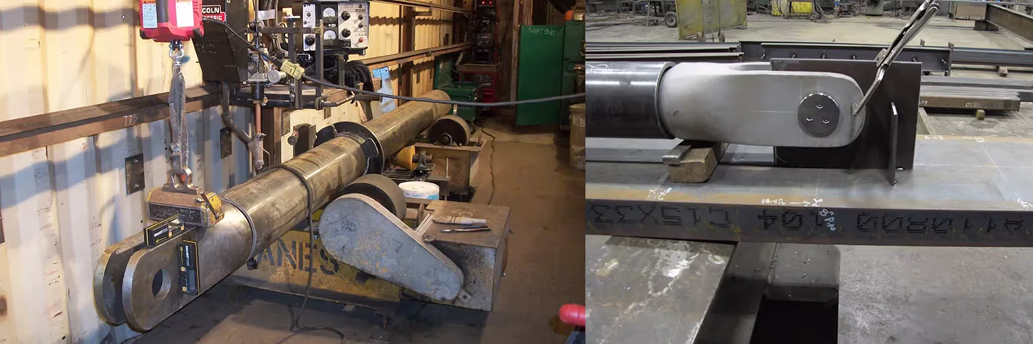
Fabrication of round HSS members equipped with UPCs is very straightforward and lends itself very well to automation. Product users need only cut the HSS member to length (no weld preparation is necessary as the castings are provided with a weld shoulder cast into their nozzle end), fit the connectors to the ends of the members, and weld the connectors to the HSS. These welds can be achieved using continuous down-hand welding with the member mounted on a turning roll. In this way, members equipped with UPCs can be processed very rapidly and with very high quality and reliability.
Another advantage offered by the Universal Pin Connectors in exterior applications is that their smooth shaping provides a superior substrate for coating system adhesion and contributes to lifecycle performance of the corrosion protection coating system. Conversely, fabricated connections feature crevices, plate edges, and weld joint pits that are notorious sites for the initiation of coating system failure.
The specification of Universal Pin Connectors in contract documents is straightforward.
The first step in specification is to determine the appropriate size of connector to utilize at each connection. Designers should download the latest product information for a listing of the current connector range, geometric information, and factored strengths/resistances. Select a connector having a strength greater than the governing factored axial design load in the connected member. Since our Universal Pin Connectors are manufactured in discrete sizes, also confirm that the selected connector matches the diameter of the member to which it is to connect. For example, a UPC-6.625 (UPC-168) only works with HSS/ Pipe members having an outer diameter of 6.625-inches (168mm). In cases where the diameters do not match, increase the size of the HSS/Pipe member to ensure geometric compatibility. In jurisdictions where connection design is not-delegated, designers need also design and check the gusset plate resistance against the factored design load (we provide guidance for that on our datasheets as well). Note that rotational fixity should be released for both strong and weak-axis flexure at the location of the pinned connection in the structural engineer's frame analysis model of the structure. In cases where both ends of the member are not pinned, the vector-sum of the axial load and shear force in the member at the pinned end should not exceed the connector's tabulated strength. Note that the connectors are not intended to transmit shear in the out-of-plane direction of the pin, nor to rotate when under load. Please reach out to our technical team with any questions or to discuss special applications - we have a lot of experience in getting more out of our connectors and are always happy to assist!
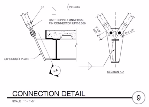
In the contract documents, Universal Pin Connectors need to be shown diagrammatically and unambiguously in the structural steel drawings, typically in connection details, bracing elevations, and/or column details. Calling specifically for Universal Pin Connectors by Cast Connex is the best way to ensure that they are incorporated into the construction of the project; however, in some instances clients prefer to include language that allows for the consideration of “approved alternates”. When alternates will be considered, it is important that the language selected ensures that if the contractors wish to make use of another connection that the design team have the final say as to the acceptability of the alternative on grounds which include structural suitability in addition to architectural performance and aesthetics.
When specifying Universal Pin Connectors, including Cast Connex-provided specification language in your project’s Division 5 specification is also strongly recommended, as it provides valuable information on product usage including but not limited to requirements for welding procedures, requirements for welds between the connector and the attaching HSS to be ground smooth (or otherwise filled and sanded, depending upon loading and coating system selection), and information on pin hardware.


.png)
